×
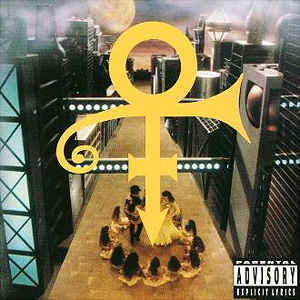
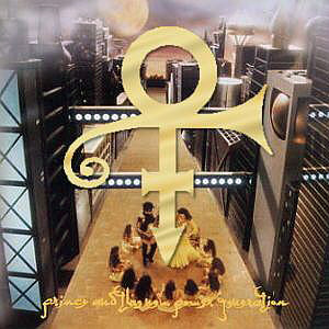
Album and CD Covers
A fair amount of technical detail is provided in certain sections—too much for some people.
How much technical information do you want when reading this?
Minimal. (Hide as much as possible.)
Moderate. (Some extras, plus options to Show More as I go.)
Full Monty. (Bring it on. I'm a geek—I can take it.)
I had been doing graphic animation and special effects on film since 1979. It was all commercial broadcast stuff done on a computer-controlled animation stand using back-light, slit-scan, and effects filters.
Around the mid 1980s I migrated to doing 3D computer-generated imagery. It was still an emerging technology. The support software needed to do 3D in a production environment just wasn't there yet and 3D rendered imagery lacked the look and feel that film effects had. So out of necessity, I wrote a lot of custom software for the production issue, and effects software that gave 3D more of a film look.
In those early years, Martha Kurtz was a designer for Minnesota Public Television and a trainer and designer for 3M’s 3D computer imagery and broadcast division. In 1987 Martha started her own company doing 3D design and animation.
In 1992 Martha and I were working together doing 3D animation and special effects under her company name Stillife & Kicking. We were leasing studio space from HDMG, a video production facility in a suburb southwest of Minneapolis. At the time, HDMG didn't have 3D graphics capabilities and we didn't have the video equipment, so it was a good relationship. We often created 3D graphics for HDMG and their clients, and in turn we gained access to their video expertise and equipment.
In April of 1992, POV Films hired HDMG to work on a video for Prince. Sotera Tschetter was the Creative Director on the project and Robert Borm the Producer. Liz Luce was employed by Sotera and was assisting on the project. Mitch Monson was a graphics artist at HDMG and was doing the video paint box effects.
The video was being produced at a frenzied pace, which, according to those that worked with him at Paisley, was par for the course on most things Prince at that time.
It was during that video production that the final version of Prince's iconic symbol was developed. I still have some of our original files from 1992 showing how that happened. So for what it's worth, this is an outline of our process, illustrated by those original files.
On the day before HDMG was scheduled to edit the final video for Prince to view, Mitch Monson asked Martha and me if we could create an animated 3D logo to use as a close to the video.... by tomorrow.
Umm, okay, and what do you have to work with?
Well, we have these drawings that Sotera and Liz have been working on...
What we didn't know at the time was that Sotera and Prince had been trying to design a new symbol for many months prior to our involvement – one that could be trademarked. Prince had been a big influence on the earlier designs which were based on elements that had special meaning to him: the Sun, the number 7, etc.
Some of their design sketches were still pretty rough. Building a 3D model to look just like the sketches would be difficult and there just wasn't time. This was, after all, still fairly early in the development of 3D graphics and nothing came easily.
The flying 3D logos Martha and I were creating in 1992 were pretty much solid shapes, extruded in the Z axis for depth. We usually added a beveled edge to the block shapes to catch highlights as they moved.
Not only would we need to build a model, but we would need to color and light it, animate it, render the animation, maybe add some effects, and then transfer the files to video in time for HDMG to edit it into the video before Prince viewed it.
We knew that the only way that was going to happen was if we simplified the artwork and made it into a single solid shape.
What follows are some of the original files that we created in the process of building the symbol. We'll be looking at two types of files that we used back then: 3D geometry files (.DAT and .obj), which describe the shape of an object, and Image files (.GEN).
Both the image and geometry files have been converted to modern formats in order to view them in web browsers. The converted geometry files are not images but are actually 2D vector graphics being drawn on the screen using the X,Y coordinates from the files. The file formats have changed but the original content displayed here has not been altered. The file names shown are of the original formats.
We didn't really know that we were creating anything of significance at the time, so most of the 'test' and intermediate files were simply deleted as we went. The files shown here are a few of those that just happen to have survived.
More information is provided in the Appendix.
What became Prince's iconic symbol was actually done in two parts.
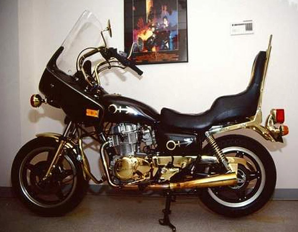
Prince had already been using a circle+arrow shape signature on lots of things. You can find many examples if you search for them. (Example on his bike.)
We created what we thought was a more proportionally-sized androgynous shape integrating the male and female symbol. We built it in a 3D modeler by generating primitive graphic shapes (circles, rectangles) and then duplicating, combining and moving the vertices until we had a nice clean shape.
Many 3D modeling packages will default to generating primitive shapes centered around the X,Y,Z coordinates 0,0,0, which is where we began.
Since all the models shown here have Z values of 0, I have removed the Z values and just used the X,Y coordinates to make Scalable Vector Graphics (SVG) elements for display. I've also added grey cross-hairs to indicate 0,0.
File: vers2.DAT
Most of the primitive shapes in this version of the model have already been joined together. Some vertices have been manually moved into position to define certain features. There are multiple geometry elements still in the file. I've labeled them Line 1-4 so you can turn them off/on.
Line 1 Line 2 Line 3 Line 4
File: vers2_1.DAT
After some pushing and pulling of vertices and joining of primitive shapes, only one element remains in this file. All other elements have been deleted.
File: vers2_2.DAT
File: vers2_3.DAT
File: vers2_4.DAT (2&3 have the same geometry but different render parameters)
The vertices that create the horizontal cross bar in this model were moved up on the stem. A bevel process was run on the outer element to create an inner element. When rendering the model, the inner element would be slightly offset in the Z axis to create a beveled edge.
We now had a solid shape that we could color, light, and animate. If we ran out of time we'd at least have this to fall back on.
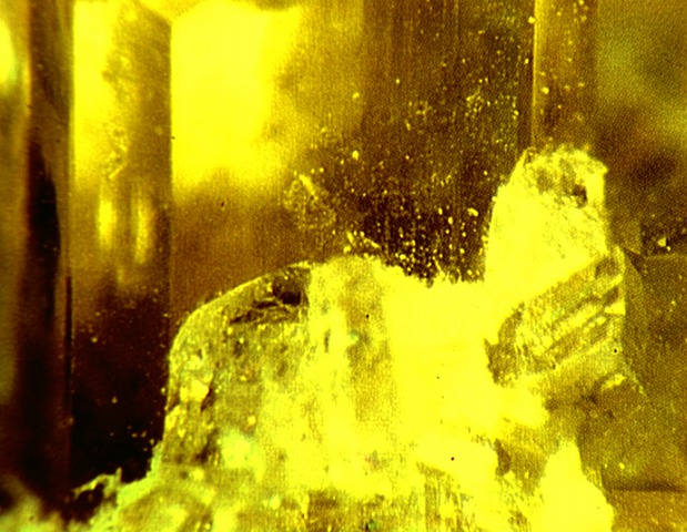
Using a video camera, we scanned a bunch of images of gemstones and ran some test renderings of the model using the gemstone images as texture maps. After several tests we ended up compositing two of the scanned images together.
We adjusted the amount of RGB values that each of the two images contributed to the composite because we wanted more yellow (explained later).
The images were NTSC 646x486 when scanned but we cut them down to 619x480 to get rid of edge noise. They are being displayed smaller in the browser simply to save screen space.
File: symtex1c.GEN (Use 37% RGB of this image)
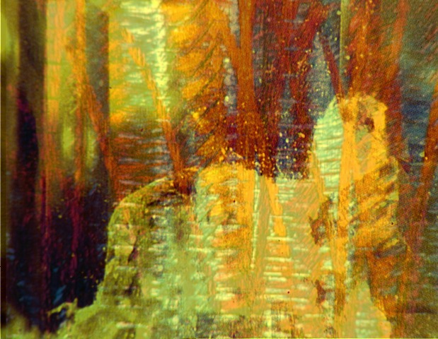
File: symtex3y.GEN (Plus 63% RGB of this image)
File: cool2.GEN - The composite texture map image.
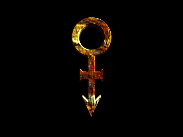
We set up an animation and rendered the model at the last frame position of the animation.
File: end_0090.GEN
This is a test render of model vers2_4.DAT, where it has been texture and bump mapped with cool2.GEN.
The render script included commands to duplicate the outline element and the bevel element by different amounts along the Z axis. This gave the rendered object both a bevel and some depth. In this rendered image, the depth is most noticeable in the 9:00 - 12:00 area of the inner circle and the upper surface of the arrow head. Since the renderer could do the Z extrusion at render time, none of the .DAT geometry files ever contained an extra set of vertices offset in the Z axis. Rendering was done at: eye 0 0 -1800, cone 40, move symbol.o 0 60 -40. Render resolution 640x481.
The androgynous model vers2_4.DAT was rendered again in the same position as end_0090.GEN but this time as solid white without any Z extrusion or texture map applied.
I've added a 3D viewer (three.js) to show model vers2_4.DAT's position in world coordinates. Camera controls: left mouse to rotate, right mouse to translate, wheel to zoom. Touch devices should be intuitive. Below the viewer is a link that will position the camera where it rendered the model for Part 2.

vers2_4.DAT in 3D Viewer. (eye 0,0,-1800, rot 0,0,0, cone 40)
Set camera to render position for Part 2.
One of Liz's or Sotera's freehand sketches was grabbed using a video camera and used as a guide in a digital paint system to make a solid white swash shape. The rendered white model from vers2_4.DAT was then composited on top of the painted white swash.
After adding the solid swash shape, the position of the cross bar didn't feel right. To save time, instead of changing the model and re-rendering, the cross bar and arrow tip were both altered in the paint system. After erasing and painting, the cross bar ended up at a lower position on the stem - more like it looked on model vers2.DAT.
File: symstat.GEN
This composite 2D paint version of the symbol was just an intermediate step in the process of creating our final 3D model.

If you bring the composite image symstat.GEN into Photoshop and do this to it...
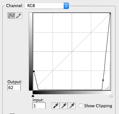
...you will see these enhanced details showing the combined elements and not so perfect paint job. Those familiar with 2D paint systems will recognize more subtle artifacts of the paint and erase process. Most obvious are uses of a circle tool—the circle outline used to make the curly tail was partially erased and then a solid circle added to make the end. The cross bar was erased and redrawn to its current position. The fact that the cross and arrow tip were not symmetrical or sharp was not a concern. That would be cleaned up in the final modeling stage.

We now had a new shape but we didn't have a 3D model of it. So we needed to make one by digitizing the composite image. Digitizing was done by displaying the image on a workstation monitor and manually clicking on points along the edge of the shape to generate X,Y coordinates which were output to a .obj (geometry) file.
File: stat.obj
This geometry file consists of digitized line segments that are a trace of symstat.GEN. The resolution of the geometry in stat.obj was not very good because the image symstat.GEN was just too small.
File: symstatBc.GEN
To get the most accurate line segments, symstat.GEN was zoomed up to a bigger size and then cut to fit on the 1024x768 workstation monitor. (Bc in the name = Bigger cut)

File: stat2.obj
This geometry file consists of the line segments digitized from symstatBc.GEN. The resolution is much better than digitizing symstat.GEN because the image was larger.
File: symbol.DAT
The digitized pixel coordinates from stat2.obj were brought into the 3D Modeler, smoothed out and cleaned up. The new 3D model was duplicated inwards to create the beveled edge that we'd want when rendering.
We now had a new model to swap into the animation.
Again using...
File: cool2.GEN
...but with different rendering parameters and no bump map, select frame positions for the animation were test rendered to check lighting. The rendering script for the animation had instructions for much more Z extrusion to be applied to make the symbol look thicker.
File: zoom_0001.GEN ... Whoa—that's too hot.

File: zoom_0030.GEN ... That's not too bad.

File: zoom_0060.GEN ... That's pretty good too.
File: zoom_0090.GEN ... It got a little dark in its final position.

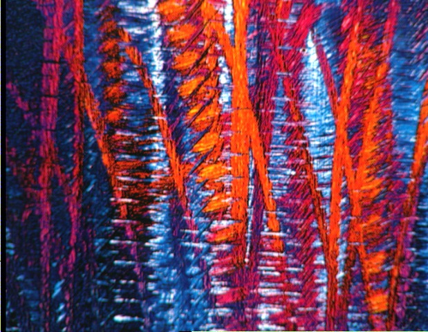
We tried running a post process on the final frame using a star filter effect. That certainly warmed it up but made it too blurry.
Then we tried a post process streak effect that smears the pixel values away from a specified point.

The streak looked pretty good, so I wrote a script that would run the streak effect on each frame of the animation 0001–0090.
11:14 pm. Apr 21, 1992 – The animation rendering was finally started
-rw-r--r--  1 dale  501    21834 Apr 21 23:14:46 1992 zoom_0002.GEN
-rw-r--r--  1 dale  501    22179 Apr 21 23:15:13 1992 zoom_0003.GEN
-rw-r--r--  1 dale  501    22504 Apr 21 23:15:41 1992 zoom_0004.GEN
-rw-r--r--  1 dale  501    22774 Apr 21 23:16:09 1992 zoom_0005.GEN
-rw-r--r--  1 dale  501    23069 Apr 21 23:16:38 1992 zoom_0006.GEN
....
....
-rw-r--r--  1 dale  501    37224 Apr 21 23:50:06 1992 zoom_0057.GEN
-rw-r--r--  1 dale  501    37944 Apr 21 23:50:57 1992 zoom_0058.GEN
11:51 pm. – The post process streak script was started. I had to wait until a bunch of frames were rendered to start the script because the post processing would run faster than the rendering. Frame 0060 was processed first. It looked okay so I let it continue on from frame 0001. (rendering was still going...)
-rw-r--r--  1 dale  501   101019 Apr 21 23:51:33 1992 zoomstk_0060.GEN
-rw-r--r--  1 dale  501    33664 Apr 21 23:51:40 1992 zoomstk_0001.GEN
-rw-r--r--  1 dale  501    35319 Apr 21 23:51:47 1992 zoomstk_0002.GEN
-rw-r--r--  1 dale  501    38749 Apr 21 23:51:48 1992 zoom_0059.GEN
-rw-r--r--  1 dale  501    36904 Apr 21 23:51:55 1992 zoomstk_0003.GEN
-rw-r--r--  1 dale  501    38524 Apr 21 23:52:02 1992 zoomstk_0004.GEN
I wrote a program to generate a second script that would run the streak effect on the last frame zoom_0090.GEN. But this second script would alter the X,Y point of origin of the streak such that the origin travels in a circle over the course of another 90 frames. So once I ran the effect on frames 0091–0180, we could loop those frames to make the effect last as long as we needed it to in the video.
#include "math.h"
main()
{
        double fy,fx;
	int frm = 91;
        for (fx = 0,fy = 1.575; fx < 6.30; fy += .070,fx += 0.070, frm++) {
		printf("gen_strkxy -n /d/prince/ima/zoom_0090.GEN \
			-h /d/prince/ima/zoom_0090.GEN \
			-o /d/prince/ima/zoomstk_%.4d.GEN -off -crv gamrev.dat \
			-sm -i 0.060000 -v -t 50 -l 1.50 ",frm);
                printf(" -cx %d",(int)((sin(fx) * 100) + 320));
                printf(" -cy %d\n",(int)((sin(fy) * 100) + 137));
	}
}
Rendering and streaking were still going...
-rw-r--r--  1 dale  501    40339 Apr 21 23:52:10 1992 zoomstk_0005.GEN
-rw-r--r--  1 dale  501    42674 Apr 21 23:52:17 1992 zoomstk_0006.GEN
-rw-r--r--  1 dale  501    44379 Apr 21 23:52:25 1992 zoomstk_0007.GEN
-rw-r--r--  1 dale  501    45499 Apr 21 23:52:33 1992 zoomstk_0008.GEN
-rw-r--r--  1 dale  501    47119 Apr 21 23:52:41 1992 zoomstk_0009.GEN
-rw-r--r--  1 dale  501    48314 Apr 21 23:52:49 1992 zoomstk_0010.GEN
-rw-r--r--  1 dale  501    49474 Apr 21 23:52:57 1992 zoomstk_0011.GEN
-rw-r--r--  1 dale  501    50989 Apr 21 23:53:05 1992 zoomstk_0012.GEN
-rw-r--r--  1 dale  501    52189 Apr 21 23:53:13 1992 zoomstk_0013.GEN
-rw-r--r--  1 dale  501    53244 Apr 21 23:53:22 1992 zoomstk_0014.GEN
-rw-r--r--  1 dale  501    40794 Apr 21 23:53:26 1992 zoom_0061.GEN
-rw-r--r--  1 dale  501    54624 Apr 21 23:53:30 1992 zoomstk_0015.GEN
-rw-r--r--  1 dale  501    55704 Apr 21 23:53:39 1992 zoomstk_0016.GEN
....
....
-rw-r--r--  1 dale  501   104269 Apr 22 00:01:23 1992 zoomstk_0062.GEN
-rw-r--r--  1 dale  501   106039 Apr 22 00:01:36 1992 zoomstk_0063.GEN
-rw-r--r--  1 dale  501   108239 Apr 22 00:01:50 1992 zoomstk_0064.GEN
-rw-r--r--  1 dale  501    46624 Apr 22 00:01:54 1992 zoom_0066.GEN
-rw-r--r--  1 dale  501   110264 Apr 22 00:02:03 1992 zoomstk_0065.GEN
-rw-r--r--  1 dale  501   112164 Apr 22 00:02:17 1992 zoomstk_0066.GEN
....
....
12:01 am. The streak process is running much faster than the renderer and catches up to it.
It can't streak frames that aren't rendered yet so I killed the streak process script. The rendering continued until finished.
....
....
-rw-r--r--  1 dale  501    82749 Apr 22 00:34:04 1992 zoom_0084.GEN
-rw-r--r--  1 dale  501    90199 Apr 22 00:36:03 1992 zoom_0085.GEN
-rw-r--r--  1 dale  501    99179 Apr 22 00:37:58 1992 zoom_0086.GEN
-rw-r--r--  1 dale  501   111174 Apr 22 00:39:55 1992 zoom_0087.GEN
-rw-r--r--  1 dale  501   126799 Apr 22 00:41:57 1992 zoom_0088.GEN
-rw-r--r--  1 dale  501   145854 Apr 22 00:45:39 1992 zoom_0089.GEN
12:45 am. Went home for a nap.
Returned and created a new script aptly named runstrkmorn
6:58 am. Started streak script to finish adding streak effect to remaining rendered images.
-rw-r--r--  1 dale  501   114514 Apr 22 06:58:23 1992 zoomstk_0067.GEN
-rw-r--r--  1 dale  501   116554 Apr 22 06:58:37 1992 zoomstk_0068.GEN
-rw-r--r--  1 dale  501   119824 Apr 22 06:58:52 1992 zoomstk_0069.GEN
....
....
....
....
-rw-r--r--  1 dale  501   480359 Apr 22 08:47:13 1992 zoomstk_0147.GEN
-rw-r--r--  1 dale  501   481499 Apr 22 08:48:06 1992 zoomstk_0148.GEN
-rw-r--r--  1 dale  501   484214 Apr 22 08:49:00 1992 zoomstk_0149.GEN
8:49 am. Apr 22 – Done. All frames rendered and streaked.
The streaked files now needed to be transferred, one frame at a time, to HDMG's video Digital Disk Recorder (DDR).
The animation was recorded both as a color layer and as a white-on-black layer, which was the matte channel from the files. The matte channel allowed the symbol to be composited on top of other video.
We recorded to DDR by loading each frame into a Video Framer buffer (VFR) on one of our workstations. Each time a frame was loaded, a command was sent to the DDR to capture the video image from the frame buffer.
All the streaked files are copied to disk "/c" which is on the workstation with the VFR, and a dope sheet script is created to record the images.
#1 85  1    "gen_vfr  -M    /c/prince/fnl/zoomstk_####.GEN"   1  85   1
63 85  1    "gen_vfr  -M    /c/prince/fnl/zoomstk_####.GEN"   63  85   1
86 86  1   "gen_vfr  -M -g 1.1   /c/prince/fnl/zoomstk_####.GEN"  86 86   1
87 87  1   "gen_vfr  -M -g 1.2   /c/prince/fnl/zoomstk_####.GEN"  87 87   1
88 88  1   "gen_vfr  -M -g 1.3   /c/prince/fnl/zoomstk_####.GEN"  88 88   1
89 89  1   "gen_vfr  -M -g 1.4   /c/prince/fnl/zoomstk_####.GEN"  89 89   1
90 180  1  "gen_vfr  -M -g 1.5   /c/prince/fnl/zoomstk_####.GEN"  90 180   1
#141 180 1   "gen_vfr  -g 1.5   /c/prince/fnl/zoomstk_####.GEN"  141 180   1
#1 90  1   gen_vfr  /c/prince/fnl/zoomstk_####.GEN   1  90   1
#91 190 +100  "gen_vfr -g 1.6  /c/prince/fnl/zoomstk_####.GEN"  90  90   1
#90 90 +300  gen_vfr -g 1.8  /c/prince/fnl/zoomstk_####.GEN  90  90   1
The matte video clip was created by copying a file's matte channel to the RGB channels of the VFR buffer. That's the -M option. The -g value option adjusted the gamma curve on the matte to make it bloom and let more of the streak through.
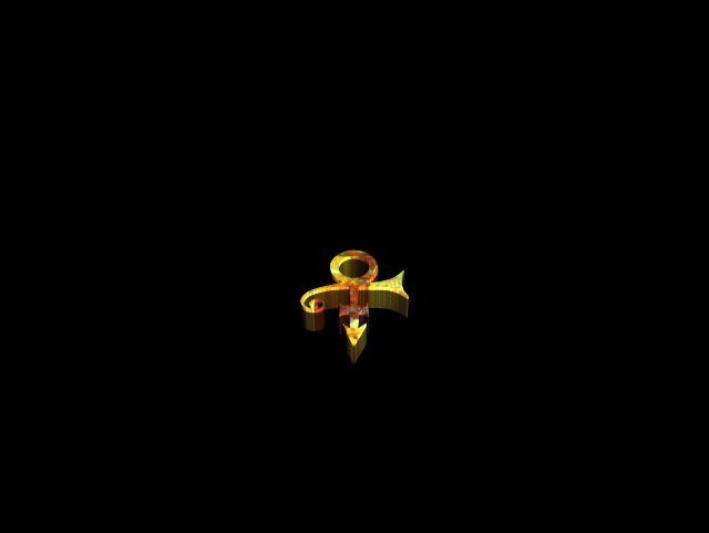
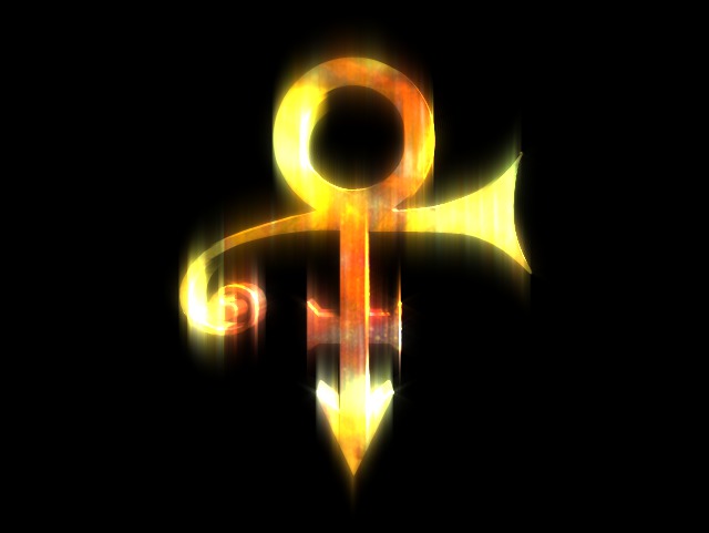
This is the resulting 3D animation (color channel only) that was composited into the video in the morning. It was the first full incarnation of the symbol that Prince ever saw.
Compressed for viewing in browser
You may be wondering why it wasn't purple. Prince had been "the purple one" prior to this symbol, but at the time we created this he was already in a yellow phase (had his BMW painted yellow, etc.), so we leaned yellow—which is what the symbol became on the album cover.
After this first design, there were some slight alterations made, but not much. For the most part, it was this original build that became the recognizable symbol.
Disk space was relatively expensive back in 1992 and the disks we had were rather limited in their capacities. So most test images that we created were deleted as we proceeded in order to save disk space. Small files like the scripts that were used to automate processes were generally left on the disks longer. They didn't take up much space and were often re-used and modified on later jobs. So the only files that remain today were those that were not deleted to make space.
It should be noted that in 1992, this symbol thing... wasn't a thing yet. It didn't exist as a whole in this form before we created it. If it had, we would have just digitized the existing one from the beginning. We didn't know we were making anything of cultural significance and we weren't even sure what Prince's reaction to it would be. It was basically "here's something we can make in a day—see if he likes it." He liked it. If I had known he was going to like it as much as he did, I would have saved more test files.
Our image files have the original creation dates and times from April 21–22, 1992, but the scripts and geometry files were transferred to a different disk before being backed up, which caused them to be dated the day they were transferred. So unfortunately we don't have the minute-by-minute play on those files.
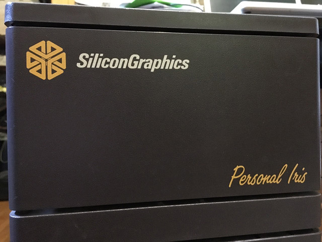
All of our work was done on Silicon Graphics Inc. 4D series Personal Iris workstations with the IRIX Operating System. The workstations were running Network File System (NFS) to share disks. One SGI workstation had the Video Framer Board (VFR) option installed. The VFR board allowed us to import still images from a video camera and to output to a video digital disk recorder (DDR).
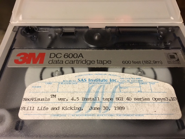
The main 3D modeling and rendering engine was NeoVisualsTM (NeoVisuals (c) 1988, 1989 by SAS Institute Inc.). Image files created by NeoVisuals were a custom binary run length encoded .GEN format. The 3D geometry files that NeoVisuals created (.DAT and .SCR) were also a custom format but for the most part were readable ASCII files.
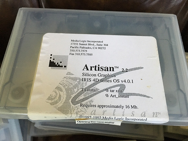
The paint software we used was ArtisanTM from Media Logic Inc., which at that time was about the only valid paint system available on the SGI—and only 16Mb! (I still have the tape of version 1.1 too. It was only 8Mb.)
The rest of the software we used were custom applications that I wrote in C. My digitizing software could write .DAT files and .obj files (a Wavefront format). My image post-processing effects generators and compositing software could read and write .GEN files. The video recording software pieces were all custom with the exception of gen_vfr for the VFR buffer. That was a version of SGI's display.c that I modified to work with .GEN files and added the matte and gamma features to it. All the scripts for managing the renderings and recording were happily done with the vi editor, which I still use. (vim)
Not surprisingly, the hardware and software that we used to create the images and geometry are no longer in use or supported. NeoVisuals' file formats .GEN and .DAT are obsolete. There are no available converters that I know of—not even ImageMagick or Gimp convert .GEN files.
In order to view the obsolete .GEN image format, I have resurrected and updated some of my old C code and re-complied it on a MacBook Pro. That way I could convert the original files to a raw rgba image format, which I then ran through ImageMagick to convert to .jpg. This makes them viewable on a more modern display platform—the web browser. It also allowed me to bring the composite file into Photoshop to view the paint artifacts.
To display the original geometry/model files, I have converted them to Scalable Vector Graphics (SVG) elements, which also display in modern browsers.
In both image files and geometry models, the data has not been altered. Only the format has been updated.
In the 3D graphics world where all of our models were built, positive Y is up. In the web browser world however, positive Y is down. If we display the original model files in the browser exactly as they are, they would look flipped upside down.
The models from Part 1 (androgynous symbol) were created around 0,0, which means that half of the vertices are in negative X space. If displayed in a browser exactly as they are, half the model would be off the left side of the screen/viewport, in addition to being flipped.
Therefore a transform="translate(308,308) scale(1.0,-1.0)" has been applied to the Part 1 SVG elements to put them in the browser's viewable X,Y space.
The 3D viewer I've inserted to view the androgynous model uses the viewport's height to calculate the cone angle. NeoVisual used the width. So for accurate viewing in the browser, I've scaled the cone by the aspect ratio .75 (480/640) to get the same view as NeoVisuals.
The Part 2 models (with swash) are digitized screen coordinates, so those models are all in positive X but are still flipped in Y. Those files have a transform="translate(0,722) scale(1.0,-1.0)" applied.
All of the files shown here were recovered from two backup tapes and one old hard drive. I have more of both to look through still, so there may be more that can be recovered. How I recovered some of this is in itself an interesting story. The hardware and magnetic tape drives that the backup tapes were created on are also obsolete. So just how do you log into a Unix machine 24 years later? Well, if you have an old green screen terminal and you left a getty running... Wait... you'll need a password.
Update: March 2018.
I finally got around to posting the story on how I recovered the files.
–Dale
If you enjoyed this page – drop me a note.